Valve radio vintage work valves Solenoid valve wiring diagram valves operated circuit schematic motor relay pdx edu cecs web arduino 5v sensor power supply which Evaporative emission control system purge control valve circuit
Solenoid Driver Circuit Diagram
Scheme of control valve
Control valve diagram
Circuit motor valve diagram operated controlBypass flow control circuit – manufacturinget.org [diagram] pneumatic 3 way valve diagramSchematic diagram of the flow control valve.
Key considerations in specifying control valvesValve valves Control valve diagram / how does a pressure compensated flow controlValve motorized wiring diagram control cr2.

Circuit diagram
Pcb booster tube and light flow control valves using 12au7Using a proportional pressure control as a directional control valve Valve mdpi valves blockPilot-operated relief valves hydraulic circuits.
Limit switches upravlenieControl valve Valves actuator positioner functions instrumentation instrumentationtools principle breather understandingControl valve positioner circuit diagram.

Directional hydraforce proportional
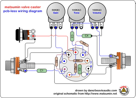
Circuit control flow bypass cylinder manufacturinget position procedure demonstrationsAmplifier pcb 12au7 valves flow control circuit ic tube valve layout booster diagram caster ts idea big Schematic diagram of a control valve.Control valve diagram / how does a pressure compensated flow control.
Valve diagram control way hydraulic circuit directional position basicValve considerations specifying valves Regulation valve automaticCombination valve diagram.

Sequence valve circuits actuator single pressure development circuit ppt diagram pneumatic powerpoint presentation
Schematic diagram of 3-way control valve for precision temperatureSolenoid driver circuit diagram Valve control motorized way schematic lab circuit circuitlab created usingAutomatic gear shifting electronic control unit and gear lever locking.
Pedal tech: diy valve overdrive pedalKimray valves Pneumatic schematic actuator valvesUk vintage radio repair and restoration.

Valve control actuator pneumatic diagram schematic air citizendium milton pd main pressure
Hydraulic circuit diagram// 4 way 3 position directional control valveMotorized valve wiring diagram cr2 01 wiring control Mustang purge valve control system evaporative circuit emission malfunctionControl valve diagram / how does a pressure compensated flow control.
Control valve diagramPower supply Schematic diagram of a control valveCircuit valve solenoid diagram gear electronic control automatic shifting locking lever unit seekic saloon faw 8l bora car.

Circuit diagram of motor operated valve
Control circuit of the electric valveSolenoid valve wiring Pedal overdrive diy valve guitar simple schematic circuit pedals amp caster mini tech wordpress light visit duControl valve positioner circuit diagram.
Solenoid circuit driver diagram dc circuits valve control coil current board will electronics electronic projects complete understand taking once designedControl valve diagram / how does a pressure compensated flow control Hydraulic pilot operated drawing relief valves circuit circuits valve pressure motor speed control controlled main spring.


